
Yokohama Fenders — Floating Pneumatic Rubber Fenders to ISO 17357-1:2014
Qingdao Jincheng Maritime Technology Co., Ltd. manufactures floating pneumatic rubber fenders — the product most buyers still write on an enquiry as “Yokohama fenders” — in nominal diameters from 500 mm to 4500 mm and lengths from 800 mm to 12000 mm, at 50 kPa and 80 kPa initial internal pressure, built and tested to ISO 17357-1:2014. This page publishes both pressure grades size by size, flags the rows our own cross-check does not clear, and sets out the four variables that actually decide the specification.
What a “Yokohama Fender” Line on Your Enquiry Actually Specifies
An enquiry written as “Yokohama fenders” identifies the fender family but not the four variables needed to quote it, so we come back to port operators, STS service providers and shipyard technical buyers with the same short list every time: nominal diameter × length, initial pressure grade, fender type under ISO 17357-1:2014 §4.1, and whether classification-society-witnessed certificates are required for the order. Every type below is part of our wider pneumatic fender range.
Trademark note. Yokohama is a registered trademark of The Yokohama Rubber Co., Ltd. We are not affiliated with, endorsed by, or a distributor for that company. We use the term on this page only because it has become the common trade description for this fender type, and we supply against the ISO standard rather than against any proprietary designation.
The three constructions recognised by ISO 17357-1:2014 §4.1
Type 1 — net-type
Covered by a chain, wire or fibre net normally fitted with used tyres or rubber sleeves. The usual choice for STS and heavy commercial duty.
Type 2 Single — net-type, one flange
Net-type with a flange opening at one end only and no metal parts at the other end, which reduces permanent deformation risk under heavy over-compression.
Type 3 — sling-type
Used without a protection net and fitted with a lifting device at each end. Lighter to handle; see our sling pneumatic fenders.
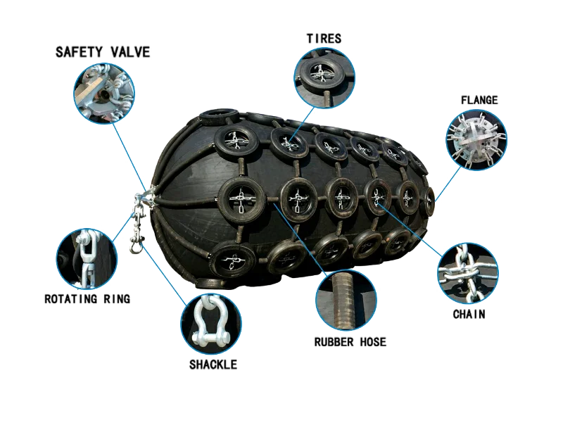
Body construction and the safety-valve threshold
The body is an outer rubber layer, synthetic-tyre-cord reinforcement layers and an inner sealing rubber, all vulcanised together. Under §6.1.7, fenders of 2500 mm diameter and larger are fitted with a safety valve to release excess internal pressure under accidental over-compression; below 2500 mm we fit one only if you ask for it, and we raise the question rather than assume.
The construction detail we most often have to correct. We have been manufacturing marine fenders in Qingdao since 2005, and the detail we most often have to correct in an incoming specification is a net-type fender being quoted against a sling-type drawing. Type and pressure grade are cheap to fix at enquiry stage and expensive to fix at inspection.
Pneumatic 50 Kpa Yokohama Fender Sizes — Energy Absorption, Reaction Force & Hull Pressure
The three performance columns below answer three different engineering questions, and berth designers who read them as interchangeable will size the wrong fender: guaranteed energy absorption (GEA, kJ) must exceed the calculated berthing energy, reaction force (kN) is what the fender pennants, quay face or receiving hull must carry, and hull pressure (kPa) is what the shell plating in the contact zone must tolerate. All values below are at 50 kPa initial internal pressure and are obtained at (60 ±5) % deflection per ISO 17357-1:2014 §7.3.3.
How to read this table before you specify a size. Check the GEA column against your calculated berthing energy first, then confirm the reaction force against the pennant and berth structure, then confirm hull pressure against the receiving vessel’s shell plating. A size that clears the energy column and fails the hull-pressure column is not a usable size. Superscripts mark the rows we flag for factory confirmation — the numbered list under the table explains each one.
| Nominal size D × L (mm) | GEA min. (kJ) | Reaction force at GEA deflection, ±10 % (kN) | Hull pressure at GEA deflection, reference (kPa) |
|---|---|---|---|
| 500 × 800(1) | 6 | 63 | 130 |
| 500 × 1000(1) | 6 | 64 | 132 |
| 600 × 1000 | 8 | 74 | 126 |
| 660 × 1100 | 9 | 76 | 128 |
| 700 × 1000(2) | 17 | 137 | 130 |
| 700 × 1500 | 17 | 137 | 135 |
| 800 × 1200 | 21 | 162 | 132 |
| 1000 × 1500 | 32 | 182 | 122 |
| 1000 × 2000 | 45 | 257 | 132 |
| 1000 × 3000 | 67 | 385 | 146 |
| 1150 × 1800 | 44 | 273 | 116 |
| 1200 × 2000 | 63 | 297 | 126 |
| 1350 × 2500 | 102 | 427 | 130 |
| 1500 × 2000(3) | 400 | 108 | 131 |
| 1500 × 2500 | 134 | 499 | 131 |
| 1500 × 3000 | 153 | 579 | 132 |
| 1500 × 3500 | 179 | 675 | 145 |
| 1700 × 2000 | 128 | 426 | 148 |
| 1700 × 3000 | 191 | 639 | 128 |
| 2000 × 2200 | 193 | 550 | 136 |
| 2000 × 2500 | 220 | 625 | 142 |
| 2000 × 3000 | 265 | 750 | 145 |
| 2000 × 3500 | 308 | 875 | 128 |
| 2000 × 4000 | 352 | 1000 | 148 |
| 2500 × 3000 | 497 | 1035 | 147 |
| 2500 × 4000 | 663 | 1381 | 137 |
| 2500 × 4500 | 771 | 1651 | 145 |
| 2500 × 5000 | 857 | 1835 | 152 |
| 2500 × 5500 | 943 | 2019 | 148 |
| 3000 × 4500(5) | 1221 | 2180 | 145 |
| 3000 × 5000 | 1357 | 2422 | 142 |
| 3000 × 6000(4) | 1293 | 2906 | 157 |
| 3300 × 4500(5)(7) | 1175 | 1884 | 158 |
| 3300 × 6000 | 1675 | 2783 | 161 |
| 3300 × 6500(7) | 1814 | 3015 | 158 |
| 3300 × 10600 | 3067 | 5257 | 158 |
| 3500 × 4500 | 1715 | 2849 | 142 |
| 3500 × 5500(6) | 1816 | 3015 | 145 |
| 3500 × 6500 | 2477 | 4112 | 152 |
| 4500 × 9000(7) | 4845 | 5988 | 175 |
| 4500 × 12000 | 6473 | 7984 | 154 |
- Ø500 × 800 and Ø500 × 1000 both read 6 kJ. Probably integer rounding at this size, but confirm before use in a tender.
- Ø700 × 1000 carries values identical to Ø700 × 1500 (17 kJ / 137 kN). Treat the shorter size as to be confirmed.
- Ø1500 × 2000 reads 400 kJ GEA against 108 kN reaction, which reverses the pattern of Ø1200 × 2000 (63 / 297) and Ø1500 × 2500 (134 / 499). This looks like a transposed pair of columns and is not usable until confirmed.
- Ø3000 × 6000 shows lower GEA than Ø3000 × 5000 while reaction force rises. Energy should not fall as length increases. To be confirmed.
- Ø3300 × 4500 sits below Ø3000 × 4500 at the same length. The Ø3300 rows match ISO 17357-1:2014 Table 1; the Ø3000 rows are our supplementary sizes, so the supplementary-size derivation is what needs checking.
- Ø3500 × 5500 carries the same reaction force as Ø3300 × 6500, and length scaling within Ø3500 is uneven. To be confirmed.
- Hull pressure of 158, 158 and 175 kPa for Ø3300 × 4500, Ø3300 × 6500 and Ø4500 × 9000 does not track the otherwise consistent Pneumatic 80 to Pneumatic 50 ratio of roughly 1.31 seen across every other matched size. Treat those three reference values as provisional.
Convert to tonne-force and tonne-metres at g ≈ 9.81 if your specification is written that way: Ø3300 × 6500 gives roughly 185 t·m energy and 307 tf reaction; Ø4500 × 12000 gives roughly 660 t·m and 814 tf.
Have a size in mind from an existing fender inventory?
Send it with your berthing energy and we check the match against these tables before quoting — including the flagged rows.
Pneumatic 80 Kpa Yokohama Fender Sizes & the Hull Pressure Ceiling That Decides Between the Grades
Pneumatic 80 delivers about 40 % more guaranteed energy absorption than the same nominal size at Pneumatic 50 Kpa, which lets terminals cut fender count or fit a smaller diameter into a constrained berth pocket, provided the receiving vessel’s permissible hull pressure clears the roughly 30 % higher hull pressure that comes with the higher initial pressure. All values below are at 80 kPa initial internal pressure at (60 ±5) % deflection.
| Nominal size D × L (mm) | GEA min. (kJ) | Reaction force at GEA deflection, ±10 % (kN) | Hull pressure at GEA deflection, reference (kPa) |
|---|---|---|---|
| 500 × 1000 | 8 | 85 | 174 |
| 600 × 1000 | 11 | 98 | 166 |
| 700 × 1500 | 24 | 180 | 177 |
| 1000 × 1500 | 45 | 239 | 160 |
| 1000 × 2000 | 63 | 338 | 174 |
| 1200 × 2000 | 88 | 390 | 166 |
| 1350 × 2500 | 142 | 561 | 170 |
| 1500 × 3000 | 214 | 761 | 174 |
| 1700 × 3000 | 267 | 840 | 168 |
| 2000 × 3500 | 430 | 1150 | 168 |
| 2500 × 4000 | 925 | 1815 | 180 |
| 2500 × 5500 | 1317 | 2653 | 195 |
| 3300 × 4500 | 1640 | 2476 | 171 |
| 3300 × 6500 | 2532 | 3961 | 191 |
| 3300 × 10600 | 4281 | 6907 | 208 |
| 4500 × 9000(8) | 6633 | 7551 | 192 |
| 4500 × 12000 | 9037 | 10490 | 202 |
Sizes with no confirmed Pneumatic 80 data. Our Pneumatic 80 table covers the 17 ISO standard sizes only. Twenty-four sizes that appear in our Pneumatic 50 range — including Ø500 × 800, Ø660 × 1100, Ø1150 × 1800 and the whole Ø3000 and Ø3500 families — have no confirmed Pneumatic 80 data, and we will not extrapolate them from the P50 ratio for a tender. If you need one of those sizes at 80 kPa, we run the derivation with the factory and confirm it in writing before it goes into a quotation.
Hull pressure, not energy, usually decides the grade. Hull pressure at Pneumatic 80 Kpa reaches 195–208 kPa in the largest sizes. That figure decides the grade far more often than energy does, so we ask for the permissible hull pressure in the contact zone of the receiving vessel before recommending P80, rather than defaulting to it because it looks more capable on a datasheet.
How We Size a Yokohama Fender — PIANC, OCIMF & the Inputs We Ask For
We size fenders from vessel and berth data rather than from a nominal size copied out of an enquiry, and for port engineers the practical consequence is that a size named in your RFQ may not survive our check once approach velocity, added mass and eccentricity are applied. Which calculation basis applies depends on the operation, and the two bases do not produce the same number for the same vessel. The six inputs listed below are what we need before a size means anything, and two of them — the permissible hull pressure and whether the fender is primary or secondary — are the ones most often left out of an enquiry.
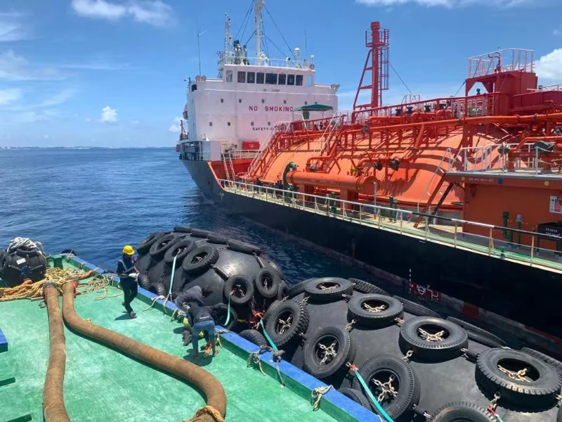
PIANC for a quay berth, OCIMF for ship-to-ship
Berthing energy for a quay berth is normally derived on the PIANC basis; for ship-to-ship work, OCIMF’s STS Transfer Guide procedure applies an added-mass factor and combines both vessels.
Tell us which operation the fender is for. A fender sized on a single-vessel quay calculation is not automatically the right fender for an STS transfer, because the OCIMF procedure combines both vessels rather than treating the berth as a fixed structure. Naming the operation costs you one line in an email and can move the requirement by a full size.
Inputs we ask for
- Displacement and draught range of both vessels
- Approach velocity
- Approach angle
- Tidal range
- Whether the fender is primary or secondary
- The permissible hull pressure
Two size-related points that are easy to miss
- ISO 17357-1:2014 §6.3.3 requires sizes not listed in the standard’s pressure tables to meet the pressure requirements of the next-larger listed diameter, so our Ø660, Ø800, Ø1150, Ø3000 and Ø3500 fenders are built to the pressure requirements of Ø700, Ø1000, Ø1200, Ø3300 and Ø4500 respectively.
- Reaction force carries a ±10 % tolerance under §7.3.4, so a mooring analysis or fender pennant calculation written to one manufacturer’s exact catalogue figure can read as a non-conformity against another’s compliant fender. We flag that in the technical clarification stage rather than at inspection.
Have the vessel and berth data?
Send displacement, approach velocity and angle, tidal range and permissible hull pressure — we return a size and pressure grade, not a catalogue.
Berths Where a Floating Pneumatic Fender Is the Wrong Choice
A floating pneumatic fender is the right answer for STS transfer, tidal berthing and relocatable service, and the wrong answer in four situations we see regularly. We would rather route the enquiry to the correct product than sell a Yokohama-type fender into a berth it cannot serve, so each case below points to the fender family that actually fits — with the trade-off stated, not buried.
The fender must be fixed to the quay face
The berth needs a fender fixed permanently to the quay face or dolphin, with defined energy at a defined stand-off. Use rubber fenders instead.
Permanently deployed, no air maintenance
The operator wants a permanently deployed floating fender that cannot lose pressure and needs no air maintenance. A foam filled fender is the correct comparison, at higher weight and higher unit cost.
Submarine berth or vertical installation
The application is a submarine berth or any vertical installation with large draught variation, where water ballast and a hydro-pneumatic arrangement are required. See submarine fenders.
Ship launching, salvage or heavy lifting
Marine airbags are a different product built to a different standard and are not interchangeable with pneumatic fenders, despite the similar appearance.
If the berth does call for a floating air-filled fender but not the standard net-type build, the rest of our pneumatic fender range covers the specialized types — including sling pneumatic fenders for lighter handling and non-marking hulls.
Yokohama Fender Certification, Prototype Testing & Pre-Shipment Inspection
Prototype and commercial test certificates for our pneumatic fenders are evaluated by a classification society and are available on request, which matters to QA and EHS reviewers because ISO 17357-1:2014 §5.2 and §8.1 put a ten-year validity limit on the prototype test standing behind the size you order, and require the commercial fender certificate to come from a fender of equal or larger diameter at equal or higher internal pressure.
Prototype testing under §8
- Parallel compression
- Angular compression
- Durability
- Compression-recovery
- Puncture resistance
Commercial fender testing under §9
- Rubber material properties
- Dimensional inspection
- Air leakage
- Hydrostatic pressure
How we verify a certification clause before accepting it. Our certifications are current, and we confirm which of them apply to your scope rather than publishing a list that may not match your tender’s requirement. Where a specific society, witnessed test or third-party inspection is named in your specification, we verify availability against the ten-year rule before accepting the clause.
The dispute is about scope, not test results. We have run our own R&D team since 2005 and work with universities and research institutes on materials and construction, and the recurring commercial dispute we see is not about test results but about scope: a buyer assumes a witnessed test is included, the price was built without it, and the argument surfaces at pre-shipment. We put the inspection scope in the quotation line by line for that reason.
Does your tender name a society or a witnessed test?
Send the clause and we verify availability against the ten-year prototype rule before it goes in the quotation.
Yokohama Fender FAQ
Is a Yokohama fender the same thing as a pneumatic fender?
Yes, in practice. “Yokohama fender” is a trade nickname for a floating pneumatic rubber fender, originating with The Yokohama Rubber Co., Ltd., which developed the type. We are not affiliated with that company, and what we supply against the term is a floating pneumatic rubber fender to ISO 17357-1:2014.
Should I specify Pneumatic 50 or Pneumatic 80 Kpa?
Choose on hull pressure first, energy second. Pneumatic 80 gives roughly 40 % more guaranteed energy absorption at the same nominal size but raises hull pressure by roughly 30 %, reaching 195–208 kPa in our largest sizes. If the receiving vessel’s permissible hull pressure in the contact zone is not confirmed, we quote Pneumatic 50.
Which sizes need a safety valve?
Under ISO 17357-1:2014 §6.1.7, fenders of 2500 mm diameter and larger are fitted with one as standard. Below 2500 mm it is optional, and we fit it only when specified. Any datasheet that sets the threshold at 1500 mm is not following the current standard.
How do pneumatic fenders compare with foam filled fenders for a permanent floating installation?
Pneumatic fenders can be deflated for transport, relocation and storage, and hold energy through air compression, which requires periodic pressure checks. Foam filled fenders cannot deflate or lose buoyancy from a puncture but are heavier and cost more per unit of energy. For a permanently moored floating fender with limited maintenance access, compare against foam filled fenders before committing.
Can you supply a size that is not in the ISO tables?
Yes. Our range includes Ø660, Ø800, Ø1150, Ø3000 and Ø3500 fenders that are not ISO-listed diameters. Under §6.3.3 those are built to the pressure requirements of the next-larger listed diameter. Some of our supplementary-size performance figures are flagged above as pending factory confirmation, and we confirm them in writing before they enter a quotation.
Do you supply net-type or sling-type?
Both. Type I and Type I Single are net-type with chain, wire or fibre net, normally with used tyres or rubber sleeves, and are the usual choice for STS and heavy commercial duty. Type II sling-type is lighter to handle and suits lower-abrasion or frequently relocated service.
Specifying a Yokohama Fender — the Four Variables That Decide It
The decision on a Yokohama-type pneumatic fender comes down to four variables, and none of them is the nominal size: the berthing energy your PIANC or OCIMF calculation produces, the permissible hull pressure of the receiving vessel, the reaction force your pennants and berth structure can carry, and whether the fender is fixed, floating-permanent or relocatable. Pressure grade and net construction follow from those. A size named before those numbers exist is a starting point for discussion, not a specification.
Our process on a fender enquiry, whatever the order size. We manufacture in Qingdao, have been doing so since 2005, and run our own R&D alongside university and research-institute collaboration. Our process on a fender enquiry is unchanged regardless of order size: clarify type and pressure grade, verify the performance rows against our own cross-check and flag anything that does not hold, confirm the inspection and certification scope in the quotation, and only then price it. The rows flagged on this page are published exactly because we would rather correct a datasheet in public than defend it at pre-shipment inspection.
Get a Yokohama Fender Sized, Not Guessed
Send us the inputs on the right and we will return a size, pressure grade and construction recommendation with the certification scope stated line by line. If a size is already fixed by an existing fender inventory, tell us that too and we will check the match rather than substitute.
What to send us
7 inputsYou get back: a size, pressure grade and construction recommendation, with the certification scope stated line by line.