
D Type Rubber Fenders for Dock Edges, Pontoons & Workboats
We manufacture D type rubber fenders — extruded rubber with a flat mounting back and a curved contact face, the most widely used dockside protection. They run continuously along a dock edge, absorb berthing impact at a strong reaction force, and install easily: anchored or bolted, and pre-bent, chamfered, drilled, or pre-cut to fit. We supply hollow D-bore, O-bore, and solid profiles in sizes from DD100 to DD500, in natural or synthetic rubber such as EPDM and butyl for ageing resistance, with a service life of 5 to 20 years. We manufacture under ISO 9001, ISO 14001, and ISO 45001 systems and have made marine fenders in Qingdao since 2005.
Where D Type Rubber Fenders Earn Their Place
D type fenders suit dock edges, pontoons, and workboats that need simple, continuous edge protection — provided the size and rubber suit the berthing energy. We use them at ports, harbours, and marinas, on tugs, workboats, and other vessels, and on framed piers and boat ramps where the narrow base fits the structure. We size the profile and rubber from your berthing energy rather than fitting a single section everywhere.
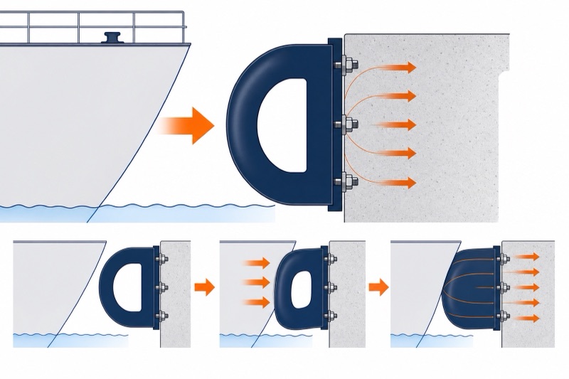
How the fender absorbs energy
The flat back bolts to the dock edge or hull and the curved face takes the contact. As a vessel pushes against it, the D-section deflects and converts the kinetic energy of the berthing into deformation energy, absorbing the impact and spreading the contact force along the edge so neither hull nor structure is point-loaded.
This is simple, low-cost edge protection rather than a high-energy berth fender. Its strength is that it runs continuously, mounts at any angle, and can be cut and drilled to fit; where a berth needs high energy absorption at a controlled reaction, a cone or cell fender is the right type instead.
Why a D fender over a cone or cell. The D-section is the cheap, easy, continuous edge protection for marinas, pontoons, and workboats — pre-bent and cut to the edge, mounted at any angle. The trade-off is low energy absorption; for a high-energy berth taking large vessels, a super cone or super cell rubber fender is the right type.
Marinas & jetties
Continuous edge protection for pontoons, jetties, and small-craft berths, cut and bent to follow the edge.
Tugs & workboats
Hard-wearing rubbing strips along the gunwale and working edges of tugs, workboats, and service craft.
Framed piers & boat ramps
The narrow base fits framed piers and boat ramps, slotting into existing structures where a wider fender will not.
Profiles, Sizes & Indicative Performance
Extruded fenders come in two standard families — the D-section (D / DD series, flat back with a curved face) and the square DC section — plus the reinforced DR type. Sizes run from 100 to 500 mm in both families. The tables below give rated reaction force and energy absorption per metre of length at 50% deflection, together with the section geometry and the fixing hardware.
D / DD series — rated performance
| Model | Reaction force R (kN/m) | Energy absorption E (kN·m/m) |
|---|---|---|
| DD100 | 77 | 1.4 |
| DD150 | 115 | 3.2 |
| DD200 | 150 | 5.7 |
| DD250 | 191 | 8.8 |
| DD300 | 230 | 12.9 |
| D300×360 | 324 | 14 |
| DD350 | 268 | 17.6 |
| DD400 | 306 | 23 |
| D500 | 418 | 31 |
| DD500 | 383 | 35.9 |
Rated at 50% deflection, per metre of fender length.
D / DD series — section geometry & fixing
| Spec. | A | B | C | D | h | ΦE | ΦF | G | H | Flat bar | Bolt | Weight (kg/m) |
|---|---|---|---|---|---|---|---|---|---|---|---|---|
| DD100 | 100 | 100 | 50 | 50 | 25 | 40 | 20 | 100-150 | 200-300 | 40×8 | M16 | 8.7 |
| DD150 | 150 | 150 | 75 | 75 | 37.5 | 50 | 25 | 100-150 | 200-400 | 60×10 | M20 | 19.6 |
| DD200 | 200 | 200 | 100 | 115* | 35* | 60 | 30 | 100-150 | 300-500 | 80×14 | M24 | 32.9 |
| DD200 | 200 | 200 | 100 | 100 | 50 | 60 | 30 | 100-150 | 300-500 | 80×14 | M24 | 34.8 |
| DD250 | 250 | 250 | 125 | 125 | 62.5 | 65 | 33 | 100-200 | 300-500 | 90×14 | M27 | 54.4 |
| DD300 | 300 | 300 | 150 | 185* | 40* | 65 | 35 | 100-200 | 300-600 | 110×16 | M30 | 72 |
| DD300 | 300 | 300 | 150 | 150 | 75 | 65 | 35 | 100-200 | 300-600 | 110×16 | M30 | 78 |
| D360 | 360 | 300 | — | — | 40 | 65 | 35 | 100-200 | 300-600 | 120×16 | M30 | 85 |
| DD350 | 350 | 350 | 175 | 175 | 87.5 | 80 | 38 | 100-250 | 300-600 | 130×16 | M33 | 107 |
| DD400 | 400 | 400 | 200 | 245* | 55* | 80 | 40 | 100-250 | 300-600 | 135×18 | M36 | 128 |
| DD400 | 400 | 400 | 200 | 200 | 100 | 80 | 40 | 100-250 | 300-600 | 150×16 | M36 | 140 |
| D500 | 500 | 500 | — | — | 90 | 95 | 45 | 100-250 | 400-600 | 160×20 | M42 | 196 |
| DD500 | 500 | 500 | 250 | 250 | 250 | 95 | 45 | 100-250 | 400-600 | 180×20 | M42 | 218 |
Dimensions in mm, weight in kg per metre. A and B are section width and height; C, D and h are profile dimensions; ΦE and ΦF are the bore diameters; G is the end distance and H the bolt pitch; Flat bar and Bolt are the fixing-strip and bolt sizes. * marks the DD-series bore variant, which shares the nominal size with a second section of the same name — DD200, DD300, and DD400 each list two sections, differing in D and h. D360 and D500 are D-series sections without the D/h bore dimensions. Figures are for reference; the final drawing is designed from the data you provide.
DC series — square section
The DC section is square rather than D-shaped, with a round bore, and carries a higher reaction force than the D section of the same nominal size.
| Spec. | A | B | ΦC | ΦD | E | F | G | H | Flat bar | Bolt | Weight (kg/m) | R (kN/m) | E (kN·m/m) |
|---|---|---|---|---|---|---|---|---|---|---|---|---|---|
| DC100 | 100 | 100 | 30 | 20 | 25 | 10 | 100-150 | 200-300 | 50×6 | M16 | 10.7 | 160 | 1.9 |
| DC150 | 150 | 150 | 65 | 27 | 30 | 12 | 100-150 | 200-400 | 60×8 | M20 | 21.8 | 240 | 4.1 |
| DC200 | 200 | 200 | 75 | 30 | 35 | 15 | 100-150 | 300-500 | 80×10 | M24 | 40.7 | 320 | 7.2 |
| DC250 | 250 | 250 | 100 | 33 | 45 | 20 | 100-200 | 300-500 | 100×12 | M27 | 62.3 | 395 | 11.5 |
| DC300 | 300 | 300 | 125 | 36 | 55 | 25 | 100-200 | 300-600 | 110×12 | M30 | 89 | 480 | 15.8 |
| DC350 | 350 | 350 | 150 | 40 | 65 | 25 | 100-250 | 300-600 | 120×12 | M30 | 119 | 556 | 21.3 |
| DC400 | 400 | 400 | 200 | 45 | 75 | 30 | 100-250 | 300-600 | 130×16 | M36 | 145 | 635 | 29 |
| DC500 | 500 | 500 | 250 | 50 | 95 | 30 | 100-250 | 400-600 | 130×16 | M42 | 226 | 792 | 45 |
Dimensions in mm, weight in kg per metre, R and E per metre at 50% deflection. Figures are for reference only; the final drawing is designed from the detailed data you provide.
The most common sizing mistake. Reading the rated figure straight. The values are per metre at 50% deflection with a ±10% tolerance, so a short fender absorbs proportionally less and the in-service reaction differs from the table. Where the berthing energy exceeds what an extruded section can take, a cone or cell fender is the right type rather than a longer run of rubbing strip.
DR Reinforced D Fender & Metal Accessories
The DR type is developed from the standard D fender with a wider base and an embedded steel frame plate, fixed to the structure with a double row of bolts. That gives higher installation strength and a longer service life than a single-row bolted D section, and it carries substantially more energy.
DR — section dimensions
| Spec. | H | W | B | D | P | Q | G | M | Weight (kg) |
|---|---|---|---|---|---|---|---|---|---|
| DR 280×540 | 280 | 540 | 430 | 40 | 41 | 82 | 165 | 120 | 125 |
| DR 300×540 | 300 | 540 | 430 | 40 | 41 | 82 | 165 | 120 | 130 |
| DR 300×600 | 300 | 600 | 490 | 40 | 41 | 82 | 165 | 120 | 144 |
DR — length, bolt count & spacing
Applies to all three DR sections (280×540, 300×540, 300×600).
| Length L (mm) | 1000 | 1500 | 2000 | 2500 | 3000 |
|---|---|---|---|---|---|
| n (bolt rows) | 2 | 3 | 4 | 4 | 5 |
| E (spacing) | 700 | 600 | 570 | 550 | 540 |
| K (end distance) | 150 | 150 | 145 | 150 | 150 |
DR — rated performance
| Value | 280H | 300H |
|---|---|---|
| Reaction force R (kN/m) | 375 | 495 |
| Energy absorption E (kN·m/m) | 14 | 20 |
Rated at 50% deflection, per metre of fender length. Performance tolerance ±10%. The DR anchor set is M36: hex bolt H 23, J 95, S 80; L-washer N 119, n 22, M 126, P 62, t 6, V 43, r 25; anchor nut a 85, b 125, e 49; anchor rod and plate T 10, L 360, G 85 (all mm).
Metal accessories — anchor bolts, flat bar & anchor plate
| Spec. | Md | Q | P | B×T (flat bar) | t | ID | OD | TP | a | b | G | L |
|---|---|---|---|---|---|---|---|---|---|---|---|---|
| 100H | M12 | 24 | 14 | 40×8 | 2.5 | 14 | 24 | 6-8 | 60 | 45 | 50 | 180 |
| 150H | M16 | 32 | 18 | 60×10 | 3 | 18 | 30 | 6-8 | 60 | 45 | 55 | 200 |
| 200H | M24 | 48 | 28 | 80×14 | 4 | 26 | 44 | 8-10 | 70 | 55 | 55 | 350 |
| 250H | M27 | 54 | 31 | 90×14 | 4 | 30 | 50 | 8-10 | 80 | 65 | 80 | 350 |
| 300H | M30 | 60 | 34 | 110×16 | 4 | 33 | 56 | 8-10 | 80 | 85 | 80 | 400 |
| 350H | M30 | 60 | 34 | 120×16 | 4 | 33 | 56 | 8-10 | 80 | 85 | 80 | 400 |
| 400H | M36 | 72 | 40 | 135×18 | 5 | 39 | 66 | 10-12 | 90 | 85 | 85 | 500 |
| 500H | M42 | 84 | 46 | 160×20 | 8 | 45 | 78 | 10-12 | 100 | 100 | 100 | 600 |
All dimensions in mm. Md, Q and P are the hex nut and washer; B×T and t the flat bar; ID, OD and TP the anchor plate; a, b, G and L the anchor bolt. All accessory information is for guidance only — every fixing design should be checked for suitability in the intended application.
Know your edge length and vessels?
Send the dock or hull edge, the craft, and the contact — we pick the profile, size, and rubber.
Profiles, Rubber & How They Are Fixed
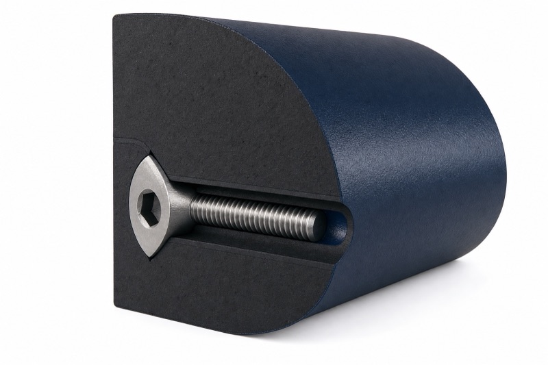
D-section in three profiles
The fender extrudes the D-section — a flat mounting back and a rounded contact face — in three profiles: a DD type with a D-shaped inner bore, an O-bore type, and a solid type. We supply high-quality rubber, natural for elasticity and abrasion or synthetic such as EPDM and butyl for weather, ozone, and heat-ageing resistance, matched to the service.
It fixes by bolt-through or anchoring, with a fixing-strip insert that stops the bolt pulling into the rubber, and it can be pre-bent, chamfered, drilled, and pre-cut to follow the edge. We confirm the fixing method and hardware with the structure rather than leave it generic.
DD type — D-bore
A D-shaped inner bore tunes the deflection and reduces weight for general edge protection.
O-bore type
An O-shaped inner bore gives a softer, more uniform deflection along the section.
DR reinforced type
The reinforced DR type widens the base and embeds a steel frame plate, fixed with a double row of bolts for higher installation strength and longer life.
When a Different Fender Fits Better
D type fenders are one option in our wider rubber fenders range, built for simple edge protection. They are not a high-energy berth fender, so here is where something else fits better.
You have a high-energy berth
For large vessels needing real energy absorption at a controlled reaction, a super cone or super cell rubber fender is the right type.
You are fendering a tug bow or stern
For the heavy push-and-pull contact on a tug, purpose-built tug boat fenders or a cylindrical fender suit better than an edge strip.
You have a floating berth
For a floating fender that rises with the tide, a pneumatic fender or foam filled fender suits better.
An honest boundary. The rated tables are per metre at 50% deflection and carry no temperature or angular correction factors, unlike our arch and cone ranges. For a berth where berthing energy actually governs, we work the corrected energy and reaction for your case before contract rather than read the catalogue figure straight.
D Type Rubber Fenders — Frequently Asked Questions
What is a D type rubber fender?
An extruded rubber fender with a D-shaped section — a flat mounting back and a rounded contact face — that runs continuously along a dock edge or hull. It absorbs berthing impact and is the most widely used dockside protection because it is simple and cheap to fit.
What profiles and sizes are available?
The D / DD series (flat back, curved face) and the square DC series, both from 100 to 500 mm, plus the reinforced DR type in 280×540, 300×540, and 300×600. Geometry, fixing-strip, and bolt sizes are in the tables; we match the profile and rubber to the edge and the contact.
How are they mounted?
By bolt-through or anchoring, with a fixing-strip insert that stops the bolt pulling into the rubber. They mount at any angle and can be pre-bent, chamfered, drilled, and pre-cut to follow the edge.
What rubber are they made of?
High-quality rubber: natural rubber for elasticity and abrasion resistance, or synthetic rubber such as EPDM and butyl for better weather, ozone, and heat-ageing resistance. We choose the compound for the service environment.
How long do they last?
Typically 5 to 20 years, depending on the rubber, the environment, and how often and hard they are used. Seawater, marine growth, UV, and contact with oils or chemicals shorten life, so we match the compound and recommend regular inspection.
When should I use a cone or cell fender instead?
When the berth has real berthing energy from large vessels. A D fender is light edge protection; a super cone or super cell fender delivers high energy absorption at a controlled reaction for a proper berth.
Match the profile to the edge and the contact
A D fender is right when its section and rubber suit the edge it protects and the vessels that touch it. Send us the edge and the craft and we return the profile, size, rubber, and fixing, with the reaction and energy worked for the run length rather than read straight off the per-metre table.
What to send us
6 inputsYou get back: a recommended profile, section size, rubber compound, and fixing method, with the confirmed dimensions for the edge.