
Super Cell Rubber Fenders for High-Energy Berths
We manufacture super cell rubber fenders whose cylindrical cell disperses the berthing energy evenly and absorbs up to 70% of the impact, protecting the largest cargo ships, tankers, and passenger vessels. They come in 13 sizes from 500H to 3000H and in five reaction grades — RE, RS, RH, RO, and RL — so the same energy can be met at the reaction force your quay allows, rated at 52.5% and 55% compression. The body is high-strength natural and synthetic rubber with a low-friction UHMW-PE front pad, a design life of more than 10 years, and manufacture under an ISO 9001 quality management system. We have made marine fenders in Qingdao since 2005, and we size the cell and grade against your berthing energy.
Where Super Cell Rubber Fenders Earn Their Place
Super cell fenders suit high-energy berths for the largest vessels, where you need a lot of energy absorbed and the reaction force tuned to the quay — provided the foundation can take the bolts and the grade is confirmed. We use them on commercial and naval berths and offshore platforms, and we size the cell and the reaction grade from your berthing energy rather than from height alone.
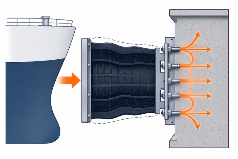
How the cell absorbs energy
The cylindrical cell deflects under the vessel and disperses the energy evenly, absorbing up to 70% of the impact while spreading the load so the hull and dock are not point-loaded. A low-friction UHMW-PE front pad lets the hull slide against the face, reducing wear during the contact.
What sets the cell apart is the choice of reaction grade. The same size is offered in five rubber grades, from ultra-high to low reaction, so we can meet your berthing energy at the reaction force an old or sensitive quay can take — rather than forcing one fixed reaction on every berth.
Why a cell over a cone or cylindrical fender. The cell delivers high energy in a compact, single-cell unit and lets you tune the reaction force through the rubber grade, which suits high-energy berths with a tight reaction limit. For very high energy at low reaction a super cone is the alternative; for simple, low-energy berths a cylindrical fender is simpler and cheaper.
Commercial ports & terminals
High energy absorption for the largest cargo, container, and passenger vessels, dispersing the berthing force to protect hull and quay.
Military & naval facilities
Large naval vessels and submarines, handled with high impact capacity and corrosion-resistant rubber for long, stable service.
Offshore platforms & oil and gas
Protecting platforms against vessel impact in harsh sea states, with UV and seawater resistance for a design life over 10 years.
Reaction Grades, Energy & Angular Correction
Super cell fenders are selected on berthing energy, then on the reaction grade that keeps reaction force within the quay’s limit. Every grade carries its own reaction and energy figure, at both the 52.5% rated deflection and the 55% maximum deflection. All values carry a ±10% tolerance and are corrected for berthing angle, site temperature, and impact duration by the PIANC factors below. Hull pressure is confirmed separately against the front-panel contact area.
Reading the table — five grades, two deflection points. RL, RO, RH, RS, and RE run from low to extreme-high reaction. Each grade gives a reaction force (R, kN) and an energy absorption (E, kN·m) at the 52.5% rated deflection, and a second pair at the 55% maximum deflection. Pick the grade that meets your energy inside the reaction limit your quay allows — at the same size, RE carries roughly twice the reaction of RL.
Rated performance by grade — 52.5% design / 55% maximum deflection
| Grade | Value | 500H | 630H | 800H | 1000H | 1150H | 1250H | 1450H | 1600H | 1700H | 2000H | 2250H | 2500H | 3000H |
|---|---|---|---|---|---|---|---|---|---|---|---|---|---|---|
| RL — Low | R @52.5% (kN) | 86 | 138 | 211 | 349 | 462 | 546 | 735 | 894 | 1009 | 1398 | 2085 | 2574 | — |
| E @52.5% (kN·m) | 18 | 38 | 75 | 153 | 233 | 299 | 468 | 628 | 753 | 1227 | 2060 | 2826 | — | |
| R @55% (kN) | 99 | 147 | 225 | 372 | 491 | 581 | 781 | 950 | 1073 | 1485 | 2216 | 2737 | — | |
| E @55% (kN·m) | 19 | 40 | 78 | 163 | 247 | 316 | 495 | 665 | 798 | 1299 | 2180 | 2992 | — | |
| RO — Standard | R @52.5% (kN) | 108 | 172 | 275 | 436 | 578 | 682 | 918 | 1120 | 1262 | 1746 | 2454 | 3028 | 3750 |
| E @52.5% (kN·m) | 23 | 47 | 96 | 191 | 295 | 375 | 585 | 786 | 945 | 1535 | 2425 | 3330 | 4300 | |
| R @55% (kN) | 125 | 182 | 292 | 463 | 614 | 725 | 976 | 1189 | 1342 | 1856 | 2607 | 3220 | 4217 | |
| E @55% (kN·m) | 25 | 50 | 102 | 203 | 309 | 396 | 619 | 832 | 997 | 1624 | 2566 | 3520 | 4635 | |
| RH — High | R @52.5% (kN) | 140 | 224 | 355 | 567 | 750 | 886 | 1193 | 1453 | 1640 | 2270 | 3188 | 3937 | 4482 |
| E @52.5% (kN·m) | 30 | 62 | 125 | 249 | 379 | 486 | 760 | 1020 | 1224 | 1994 | 3150 | 4322 | 5160 | |
| R @55% (kN) | 160 | 237 | 378 | 603 | 798 | 942 | 1269 | 1544 | 1743 | 2413 | 3390 | 4182 | 5099 | |
| E @55% (kN·m) | 32 | 67 | 132 | 264 | 401 | 516 | 804 | 1080 | 1300 | 2111 | 3336 | 4576 | 5510 | |
| RS — Super high | R @52.5% (kN) | 162 | 258 | 412 | 655 | 865 | 1022 | 1376 | 1676 | 1892 | 2619 | 3679 | 4543 | — |
| E @52.5% (kN·m) | 36 | 72 | 145 | 287 | 437 | 561 | 876 | 1177 | 1413 | 2300 | 3628 | 4987 | — | |
| R @55% (kN) | 187 | 274 | 437 | 696 | 920 | 1087 | 1464 | 1781 | 2012 | 2783 | 3911 | 4829 | — | |
| E @55% (kN·m) | 38 | 76 | 153 | 304 | 463 | 594 | 928 | 1247 | 1495 | 2435 | 3848 | 5280 | — | |
| RE — Extreme high | R @52.5% (kN) | 182 | 290 | 464 | 737 | 975 | 1153 | 1551 | 1885 | 2131 | 2941 | 4145 | 5118 | — |
| E @52.5% (kN·m) | 40 | 80 | 163 | 324 | 492 | 632 | 987 | 1326 | 1591 | 2591 | 4095 | 5618 | — | |
| R @55% (kN) | 210 | 309 | 493 | 784 | 1037 | 1225 | 1649 | 2007 | 2266 | 3136 | 4406 | 5441 | — | |
| E @55% (kN·m) | 43 | 85 | 173 | 343 | 521 | 669 | 1045 | 1405 | 1685 | 2743 | 4337 | 5949 | — |
Reaction force (R) and energy absorption (E) per fender, at the 52.5% rated deflection and the 55% maximum deflection. Performance tolerance ±10%. The 3000H is produced in the RO and RH grades only. Product performance can be tailored to project requirements.
PIANC correction factors
Rated figures are corrected for berthing angle, site temperature, and impact duration before the fender is confirmed.
| Angular factor (AF) | Temperature factor (TF) | Velocity factor (VF) | |||
|---|---|---|---|---|---|
| Angle (°) | AF | Temp (°C) | TF | Time (s) | VF |
| 0 | 1.000 | +50 | 0.882 | 1 | 1.005 |
| 3 | 0.977 | +40 | 0.926 | 2 | 1.002 |
| 5 | 0.951 | +30 | 0.969 | 3 | 1.001 |
| 8 | 0.909 | +23 | 1.000 | 4 | 1.001 |
| 10 | 0.883 | +10 | 1.056 | 5 | 1.000 |
| 15 | 0.810 | 0 | 1.099 | 6 | 1.000 |
| 20 | 0.652 | -10 | 1.143 | 8 | 1.000 |
| -20 | 1.186 | ≥10 | 1.000 | ||
| -30 | 1.230 | ||||
Reference angle 0° (AF = 1.000) and reference temperature +23 °C (TF = 1.000). The angular factor falls steadily with angle, reaching 0.652 at 20°; the temperature factor rises as the rubber stiffens in cold weather. The velocity factor is close to unity across the range, so impact duration has little effect on this fender type.
Deflection response curve
Reaction and energy do not rise linearly with deflection. The cell reaches close to its full reaction early — about 98% by 25% deflection — then flattens and dips slightly before rising again, while energy continues to build. These are the percentages of the rated (52.5%) figures at intermediate deflections.
| Deflection H (%) | 0 | 5 | 10 | 15 | 20 | 25 | 30 | 35 | 40 | 45 | 50 | 52.5 | 55 |
|---|---|---|---|---|---|---|---|---|---|---|---|---|---|
| Reaction R (%) | 0 | 30 | 58 | 80 | 93 | 98 | 99 | 97.5 | 95 | 96 | 97 | 100 | 106 |
| Energy E (%) | 0 | 2 | 8 | 15 | 25 | 37 | 50 | 60 | 70 | 88 | 97 | 100 | 106 |
Worked example: at 35% deflection, R = 97.5% and E = 60% of the rated figures. For a fender rated 1,000 kN / 500 kN·m, that gives 975 kN and 300 kN·m.
The most common sizing mistake. Reading the rated table straight and ignoring the grade, the angle, and the ±10% tolerance. At the same size, RE carries roughly double the reaction of RL; at 20° the angular factor is down to 0.652; and a cold berth stiffens the rubber by up to 23%. We pick the size and grade against your energy, apply the PIANC factors, then check reaction force and hull pressure.
Frontal Panel, Anchors, Chains & Clearances
A cell fender system is the rubber body plus the frontal panel, the facing pad, the fasteners, the cast-in anchors, and the chain system. Each part has a job, and all of it is sized together from the cell model.
System components & materials
| Component | Function | Typical material |
|---|---|---|
| Rubber fender | Absorbs ship impact energy, protecting dock and vessel. | Rubber, Q235 |
| Precast nut & bolt | Fixes the fender to the dock. | Stainless steel, Q235 HDG |
| U-anchor | Holds the chains. | Q235 painted or HDG |
| Frontal panel | Bears the reaction, increases hull contact area and lowers hull pressure — below 25 t/m² where required. | Q235 / Q355 painted, or hot zinc/aluminium sprayed |
| Facing pad | Reduces the friction coefficient and protects the hull. | UHMW-PE |
| Connection bolt & nut | Fixes the fender to the frontal panel and other parts. | Stainless steel, Q235 HDG |
| Weight chain | Supports the panel weight and prevents the system drooping. | Q235 / CM490 HDG or painted |
| Tension chain | Limits deflection when the upper part of the fender is loaded. | Q235 / CM490 HDG or painted |
| Shear chain | Restrains shear deformation of the fender system. | Q235 / CM490 HDG or painted |
Precast nut — Type I (new concrete)
| Model | MD | H | J | S | N | n | M | P | t | V | r | a | b | e | T | L | G |
|---|---|---|---|---|---|---|---|---|---|---|---|---|---|---|---|---|---|
| 500H | M24 | 17 | 70 | 55 | 60 | 22 | 83 | 25 | 5 | 28 | 15 | 75 | 100 | 36 | 6-10 | 300 | 75 |
| 630H | M30 | 19 | 75 | 60 | 65 | 20 | 110 | 33 | 5 | 34 | 15 | 75 | 105 | 38 | 8-12 | 330 | 85 |
| 800H | M33 | 23 | 85 | 70 | 70 | 25 | 117 | 35 | 5 | 36 | 15 | 85 | 120 | 42 | 8-12 | 360 | 85 |
| 1000H | M39 | 26 | 95 | 75 | 80 | 26 | 148 | 40 | 6 | 43 | 25 | 85 | 125 | 49 | 8-12 | 430 | 95 |
| 1150H | M42 | 26 | 100 | 80 | 85 | 28 | 151 | 43 | 6 | 46 | 25 | 85 | 125 | 55 | 12-16 | 500 | 105 |
| 1250H | M45 | 30 | 110 | 90 | 90 | 31 | 153 | 45 | 6 | 49 | 30 | 95 | 140 | 59 | 12-16 | 500 | 125 |
| 1450H | M52 | 35 | 120 | 95 | 100 | 31 | 158 | 50 | 6 | 56 | 30 | 100 | 150 | 69 | 12-16 | 570 | 135 |
| 1600H | M52 | 35 | 120 | 95 | 100 | 34 | 158 | 50 | 6 | 56 | 30 | 100 | 150 | 69 | 12-16 | 570 | 140 |
| 1700H | M56 | 35 | 135 | 110 | 110 | 40 | 165 | 55 | 8 | 63 | 30 | 105 | 165 | 75 | 16-20 | 620 | 140 |
| 2000H | M64 | 40 | 150 | 125 | 116 | 38 | 165 | 58 | 8 | 70 | 40 | 125 | 190 | 79 | 16-20 | 700 | 150 |
| 2250H | M64 | 40 | 150 | 125 | 120 | 43 | 195 | 60 | 8 | 70 | 40 | 125 | 190 | 79 | 16-20 | 700 | 150 |
| 2500H | M64 | 40 | 170 | 125 | 125 | 50 | 202 | 65 | 10 | 70 | 50 | 125 | 190 | 79 | 16-20 | 700 | 175 |
| 3000H | M76 | 50 | 190 | 145 | 140 | 55 | 207 | 70 | 10 | 84 | 50 | 135 | 210 | 95 | 20-24 | 800 | 175 |
All dimensions in mm. Hex bolt (MD, H, J, S), L-washer (N, n, M, P, t, V, r), precast nut (a, b, e), anchor rod and plate (T, L, G). Used for installing fenders into newly poured concrete.
Anchor bolt — Type II (existing concrete)
| Model | MD | A | L | ΦS | T (nut) | N | n | M | P | t | V | r |
|---|---|---|---|---|---|---|---|---|---|---|---|---|
| 500H | M24 | 60 | 280 | 30 | 22 | 60 | 22 | 83 | 25 | 5 | 28 | 15 |
| 630H | M30 | 70 | 360 | 38 | 26 | 65 | 20 | 110 | 33 | 5 | 34 | 15 |
| 800H | M33 | 75 | 400 | 42 | 28 | 70 | 25 | 117 | 35 | 5 | 36 | 15 |
| 1000H | M39 | 85 | 460 | 50 | 32 | 80 | 26 | 148 | 40 | 6 | 43 | 25 |
| 1150H | M42 | 95 | 510 | 55 | 34 | 85 | 28 | 151 | 43 | 6 | 46 | 25 |
| 1250H | M45 | 105 | 550 | 60 | 36 | 90 | 31 | 153 | 45 | 6 | 49 | 30 |
| 1450H | M52 | 115 | 630 | 65 | 42 | 100 | 31 | 158 | 50 | 6 | 56 | 30 |
| 1600H | M52 | 115 | 630 | 65 | 42 | 100 | 34 | 158 | 50 | 6 | 56 | 30 |
| 1700H | M56 | 125 | 680 | 68 | 45 | 110 | 40 | 165 | 55 | 8 | 63 | 30 |
| 2000H | M64 | 130 | 780 | 75 | 51 | 116 | 38 | 165 | 58 | 8 | 70 | 40 |
| 2250H | M64 | 140 | 780 | 75 | 51 | 120 | 43 | 195 | 60 | 8 | 70 | 40 |
| 2500H | M64 | 150 | 780 | 75 | 51 | 125 | 50 | 202 | 65 | 10 | 70 | 50 |
| 3000H | M76 | 180 | 940 | 88 | 64 | 140 | 55 | 207 | 70 | 10 | 84 | 50 |
All dimensions in mm. Anchor bolt (MD, A, L, ΦS), nut (T), L-washer (N, n, M, P, t, V, r).
Cast-in U-anchor & chain system
| Model | Φd | R | L | A | T | ΦG | Chain links | Shackle | Tensioner |
|---|---|---|---|---|---|---|---|---|---|
| 500H | 40 | 70 | 600 | 50 | 20~30 | 100 | Φ20.5 | Φ22 | M24 |
| 630H | 40 | 70 | 600 | 50 | 20~30 | 100 | Φ20.5 | Φ22 | M24 |
| 800H | 50 | 80 | 650 | 50 | 20~30 | 110 | Φ26 | Φ28 | M30 |
| 1000H | 55 | 90 | 730 | 50 | 20~30 | 120 | Φ28 | Φ32 | M33 |
| 1150H | 60 | 100 | 780 | 50 | 25~35 | 140 | Φ32 | Φ35 | M36 |
| 1250H | 60 | 100 | 780 | 50 | 25~35 | 140 | Φ34 | Φ38 | M42 |
| 1450H | 60 | 100 | 780 | 70 | 25~35 | 140 | Φ36 | Φ38 | M42 |
| 1600H | 65 | 105 | 830 | 70 | 25~35 | 150 | Φ38 | Φ45 | M48 |
| 1700H | 65 | 105 | 830 | 70 | 25~35 | 150 | Φ40 | Φ45 | M48 |
| 2000H | 70 | 115 | 880 | 70 | 25~35 | 160 | Φ42 | Φ45 | M48 |
| 2250H | 70 | 115 | 880 | 70 | 25~35 | 160 | Φ42 | Φ45 | M48 |
| 2500H | 80 | 120 | 930 | 70 | 25~35 | 160 | Φ46 | Φ50 | M56 |
| 3000H | 80 | 120 | 930 | 80 | 25~35 | 160 | Φ46 | Φ50 | M56 |
U-anchor dimensions in mm. Chain material Q235 HDG or Gr.U2 HDG; shackles Gr.S HDG; tensioners Q235 / GR8.8 HDG. Stud-link and open-link chains, bow and dee shackles (G-2130, G-209, G-210), tensioners, and rubber shock absorbers are available. All chain and accessory information is for guidance only — every chain design should be checked for suitability in the intended application.
Minimum clearances
There must be enough space around and between the cell fenders and the steel panel to let them deflect without interference.
| Model | Edge A (mm) | Centres B (mm) |
|---|---|---|
| 500H | 510 | 700 |
| 630H | 600 | 880 |
| 800H | 700 | 1120 |
| 1000H | 850 | 1500 |
| 1150H | 990 | 1730 |
| 1250H | 1060 | 1870 |
| 1450H | 1200 | 2180 |
| 1600H | 1270 | 2400 |
| 1700H | 1470 | 2550 |
| 2000H | 1560 | 2880 |
| 2250H | 1710 | 3360 |
| 2500H | 1910 | 3730 |
| 3000H | 2240 | 4500 |
Distances are for guidance — contact us if in doubt.
Panel weight support
Cell fenders can support significant static weight. These limits give the permitted frontal-panel weight before additional support chains are required, and they differ by cell height.
| Cell height | Grade | Horizontal, single or multiple (n ≥ 1) | Vertical, multiple (n ≥ 2) |
|---|---|---|---|
| H ≤ 800 | RL — Low | WH ≤ n × 0.95 × w | WV ≤ n × 1.2 × w |
| RO — Standard | WH ≤ n × 1.1 × w | WV ≤ n × 1.45 × w | |
| RH — High | WH ≤ n × 1.3 × w | WV ≤ n × 1.75 × w | |
| H ≥ 1000 | RL — Low | WH ≤ n × 10 × w0.6 | WV ≤ n × 13.5 × w0.6 |
| RO — Standard | WH ≤ n × 15 × w0.6 | WV ≤ n × 19 × w0.6 | |
| RH — High | WH ≤ n × 19 × w0.6 | WV ≤ n × 23.5 × w0.6 |
n = number of cell fenders; w = weight of one fender; WH = panel weight for a horizontal arrangement; WV = panel weight for a vertical arrangement. Where the panel exceeds these limits, secondary support chains are added.
Know your berthing energy and reaction limit?
Send the vessel, approach speed, angle, and quay limit — we pick the cell size and reaction grade.
Construction, Mounting & Geometry
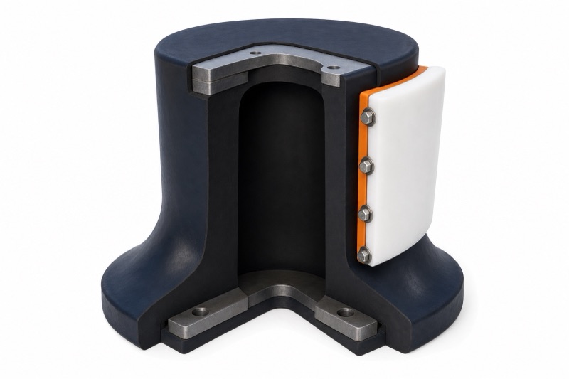
Natural and synthetic rubber, UHMW-PE face
The cell is moulded from high-strength natural and synthetic rubber for resistance to UV, seawater, and abrasion, with a design life of more than 10 years. The front face carries a low-friction UHMW-PE pad that lowers the friction against the hull and extends the life of the face.
The cell bolts to a solid foundation with 4 to 12 anchors depending on size, from M24 at the 500H to M76 at the 3000H, through bolt holes of 32 to 90 mm. Cast-in precast nuts (Type I) suit new concrete and full-shank anchor bolts (Type II) suit existing concrete. We confirm the front panel, hardware, and bolt pattern with the structure rather than leave them generic.
| Model | H | ΦW | ΦB | T | Φd | Anchors | Weight (kg) |
|---|---|---|---|---|---|---|---|
| 500H | 500 | 650 | 550 | 25 | 32 | 4-M24 | 112 |
| 630H | 630 | 840 | 700 | 30 | 39 | 4-M30 | 231 |
| 800H | 800 | 1050 | 900 | 30 | 40 | 6-M33 | 410 |
| 1000H | 1000 | 1300 | 1100 | 35 | 47 | 6-M39 | 822 |
| 1150H | 1150 | 1500 | 1300 | 40 | 50 | 6-M42 | 1220 |
| 1250H | 1250 | 1650 | 1450 | 45 | 53 | 6-M45 | 1488 |
| 1450H | 1450 | 1850 | 1650 | 47 | 61 | 6-M52 | 2330 |
| 1600H | 1600 | 2000 | 1800 | 50 | 61 | 8-M52 | 3022 |
| 1700H | 1700 | 2100 | 1900 | 55 | 66 | 8-M56 | 3730 |
| 2000H | 2000 | 2200 | 2000 | 55 | 74 | 8-M64 | 5258 |
| 2250H | 2250 | 2550 | 2300 | 60 | 74 | 10-M64 | 7452 |
| 2500H | 2500 | 2950 | 2700 | 70 | 74 | 10-M64 | 10755 |
| 3000H | 3000 | 3350 | 3150 | 85 | 90 | 12-M76 | 18582 |
Dimensions in mm, weight per fender. H is the cell height, ΦW the outer flange diameter, ΦB the bolt-circle diameter, T the flange thickness, and Φd the bolt-hole diameter. Anchors are given as count × thread size, from 4-M24 at 500H to 12-M76 at 3000H.
When a Different Fender Fits Better
Super cell fenders are one option in our wider rubber fenders range, built for high-energy fixed berths. They are not the right fender for every job, so here is where something else fits better.
You need very high energy at low reaction
Where the priority is the highest energy at the lowest reaction in a tapered unit, a super cone rubber fender is the alternative high-performance type.
You have a simple, low-energy berth
For general berths and workboats that do not need the cell’s energy or grade choice, a cylindrical rubber fender is simpler and cheaper.
You have a floating berth
For a floating fender that rises with the tide rather than a fixed bolted one, a pneumatic fender or foam filled fender suits better.
An honest boundary. The rated tables assume 52.5% deflection at +23 °C and square-on contact, and carry a ±10% tolerance. A real berth is colder or warmer, the vessel arrives at an angle, and hull pressure depends on the panel area — none of which the table shows. We work the corrected figures and the hull pressure for your case before contract rather than quote a single rated number.
Super Cell Rubber Fenders — Frequently Asked Questions
What do RE, RS, RH, RO and RL mean?
Five rubber grades from low (RL) through standard (RO), high (RH), super-high (RS), to extreme-high (RE) reaction. Each carries its own reaction and energy figure, so the same cell size can meet your berthing energy at the reaction force your quay can take — RE is roughly double RL at the same size.
How much energy does a super cell fender absorb?
The cell is rated at 52.5% design deflection with a 55% maximum, and both points are in the performance table. Each of the five grades carries its own energy figure — at 1000H, for instance, energy runs from 153 kN·m in RL to 324 kN·m in RE.
How does the berthing angle change performance?
Performance derates with angle: the angular factor is 0.883 at 10° and 0.652 at 20°. We apply the PIANC angular factor together with the temperature and velocity factors, and size to the actual berthing angle rather than read the table straight.
What is the front pad made of?
A low-friction UHMW-PE front pad, which lowers the friction against the hull and extends the life of the fender face. The mounting panel and hardware are confirmed with the structure for your berth.
How long do they last and what maintenance is needed?
The design life is more than 10 years, with the natural and synthetic rubber resisting UV, seawater, and abrasion. They need only simple maintenance and regular inspections of the rubber, the front pad, and the bolts.
When should I use a cone or cylindrical fender instead?
Use a super cone for the highest energy at the lowest reaction in a tapered unit, and a cylindrical fender for simple, low-energy berths and workboats. The cell suits high-energy berths where you want to tune the reaction force through the rubber grade.
Pick the cell and grade on energy, reaction and angle
A cell fender is right when its energy covers your berthing energy and the grade keeps reaction within the quay’s limit, corrected for angle. Send us the vessel and berth and we return the size, grade, and corrected performance — not a single rated figure.
What to send us
6 inputsYou get back: a recommended cell size and reaction grade with energy absorption and reaction force corrected for angle, plus the bolt pattern and front pad.